

 If you want to build a jointed crankbait, you will need a small wood lathe. You can use a professional lathe, but there are cheaper ones available that can be used in combination with a drill as well. And almost everyone already owns a drill. I bought the lathe I use in combination with my drill at a very low price. With some adjustments, like a running center, it is a very good tool for the fabrication of crankbaits.
The first steps
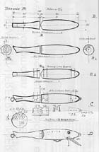
When the lathe is ready for use, we can get started. We place a piece of wood, for instance birch wood, willow wood or pinewood of 160 x 25 mm (this can be round or square) in the lathe, see drawing A-A. We begin by chiseling away the horizontal marked parts using a round sharpened chisel. After some practice you should be able to make a shape with nice, fluent lines, see drawing A-A1. You sand this shape nice and smooth, and after that, you polish it with steel wool. But be aware for your fingers. By the way, you can build this base-shape entirely using your own insight.
 Then we proceed shaping the lure, the tail-part to be exact. This goes as follows: You take the crankbait out of the lathe and remove the slanting marked part with a wood-chisel, see drawing A-A2 and B-B1 back view. Sand this part nice and smooth as well. The crossed part remaining. That finishes the first workfase. Lacquer this base-shape with a thin celluloid lacquer. This lacquer dries so fast that we can proceed with the next step after a half hour. This next step is to saw the crankbait in half, see drawing A-A4. After this, file of the sides at the ends, using a rough file. As shown on the drawings A-A5, B-B and B-B2. Lacquer these filed ends and give some time to dry. We now have the two parts of our crankbait. With a fine hobby-saw, we make the three vertical cuts. This is where we are going to put the plate with the fastening-eye, see drawing A-A6. To prevent the crankbait from damaging while doing this, you can jam it between two pieces of thick cardboard or wood board. You will need to saw these three cuts very precise and right!
Mounting the ironworks
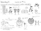
After this, we are going to build the attachment eye, see drawing B-C1 and C-C1. Then the clasps, see drawing B-C2 and C-C2, as well as the hinge, see drawing B-C3 and C-C3. Out of a piece of stainless steel, for example an old drum from a washing machine, we cut a piece of 25 x 15 mm. Adjust it until the shape in figure C-C1 arises. Then we drill the hole of 2 mm, see drawing B-C1 and C-C1. With a nail and a hammer we hammer dents in the plate, see the cross in drawing B-C3 and C-C3. Me make these dents in order to make it easier to fasten the plate and the two parts of the hinge. We proceed our work by building the clasp in which the splitring with belly hook is going to hang. We take a small strip of the same stainless steel. The sizes are 2 - 3 mm wide, 15 mm long; 1,5 mm thick, see drawing B-C2 and C-C2. Open your vice about 4 to 5 mm and put the plate of metal transverse in the vice, see drawing C-C2. We put a 3 mm thick, round nail in the middle of the plate and hammer it downwards until a rounding appears with on both sides a rim, see drawing C-C2. That gives us a clasp as shown in drawing C-C2. All you need to do is to drill to small holes of 1.5 mm at the ends of the clasp and then we can attach the clasp thoroughly with screws. Now follows the difficult task of building the hinge. But don't panic, it isn't that hard. Out of stainless steel we cut a piece of 40 x 15 mm, see drawing C-C4. We bend these pieces together, see drawing C-C4+. We take a round nail about 1,5 mm thick in our hand and hang the bended plate on it. We lower this plate into the vice. Just under the nail we close the vice and make a nice round cot. With a hammer you tap the cot until it's nice and round, see drawing C-C5. Remove the nail and use it to build the other plate in the same way. When you removed the nail out of the second plate, let it in the vice. We now have two double plates with a cot at the end, see drawing C-C6 and C-C7. Saw off the marked part of the first part, C-C6, by sawing in the cot from the top as well as the bottom. File the remaining part of the cot, removing al sharpness. Now we put the second plate in the vice again and with some sawing we remove the middle part of the cot. Again remove al sharpness with a file. The result is a double plate with two cots. Remark: If we would use thin material, say 0,5 mm thick, we can use the hinge as it is. If we use thicker material we will have to saw off one side. This is how we do this: we bend both halves of the hinge somewhat open, a little bit like in drawing C-C4+, and saw it trough on the bend of the cot. File it neat and slick and hammer in the dents. The parts C-C6 and C-C7 should fit in each other nicely see drawing C-C8.
Diving lip and attachment eye
The only thing to build is the lip. We take a round object, for example a coin, or a photo case (case of a new photo-roll). The last thing has the perfect diameter. On a piece of the well known stainless steel you draw the rounding of the photo-roll, see drawing B-C8 and C-C8. Then we cut out this circle very carefully and remove all roughness. As shown in drawing C-C9 we drill two holes of 7 mm in it. Cut in the lip along the dotted lines, see drawing C-C10. Now we drill three holes of 1,5 mm in the three strips you created, see drawing C-C11. Cut and file of all roughness and the lip is ready. Now it's time to assemble the lure. In drawing C1 and the destined slot in the front side of the crankbait, we put some glue. You can use Bison-kit as well as epoxy glue. You do the same with the two sides of the hinge and the destined slots in the middle of the crankbait, see drawing B-C3. After enough drying, according to the glues manual we put the parts in place. Let this dry completely. Then drill the holes of about 1,5 mm as shown in drawing B-C12. We drill through the plate and the hinge parts until in the crankbait. Be aware: All the way through the plate and the hinge halves, but not through the crankbait. In these holes we put the copper pins, in order for the plates to be secured. We tap these just far enough into the hole, so they won't go through the crankbait. Now we attach the lip, see drawing B-C8. In order to do this we bend the strips of the lip so that they align nicely with the crankbait, see drawing B-D1. After that screw in the screws, drill it first, and attach them thoroughly. We do the same with the clasp, see drawing B-C2. Then we screw in the screw-eye, see drawing B-C16. Drill a hole first and dip the screw eye in glue before you screw it in. All holes and openings, like the ones near the hinge and the pins, we fill with liquid wood. Let this dry and sand it smoothly and prime it. When this has dried, we assemble the two parts of the crankbait together with help of a copper nail, which is secured at the end (bottom), see drawing B-C13. We can also use a piece of stainless steel wire, see drawing C-C14; put it through the hinge and make an eye at the end (bottom). It is even possible to use a piece of copper wire, see drawing C-C15. We bend the end of the wire a bit and put it through the hinge. Then bend the other side (bottom).
To conclude this
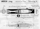
The crankbait is finished in his raw form. It needs to be painted and finished. I prefer bright colors. On my end result, see drawing B-D, I have painted the light blocks bright red and the black blocks yellow. The end result is a crankbait with an alluring action. My son Hans called this creation the 'Mega crankbait'. This because of the many pike he caught on them. Give it a try. You will see that the satisfaction of catching a pike with a homebuilt crankbait is much bigger then with a bought one...
Dirk de Boer
Source: Voor en door de Visser en Poask Hengelsport